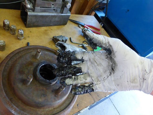
First disassembling the thing. Wow! that's a lot of grease.
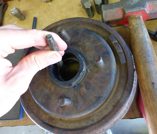
Using a punch to remove a bearing.
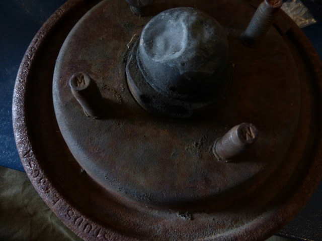
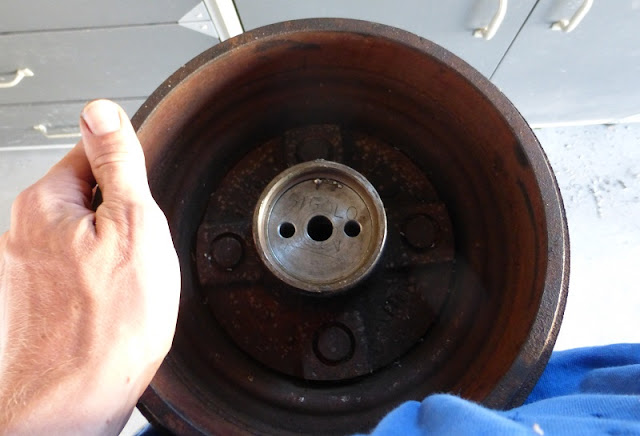
What it looked like after cleaning and removing the parts.
The bonus loot: two taper bearings, a cap, a nut, castle nut, toothed washer, cotter key, cap, etc.
Now turning an adapter for the 7/8" tubing to insert into the base.
I decided this would be fancy, so I bought some stainless tubing so it wouldn't looks like that ugly chrome plated one I have... this is the equivalent of the church buying gold candlesticks because brass aren't good enough.
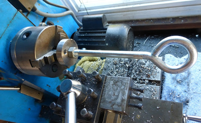
Tapping a 3/8" set screw hole in the adapter.
Then filing a flat on the 7/8 tubing.
Connected.
Now tapping some holes in the bottom to secure the adapter to the base.
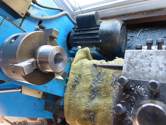
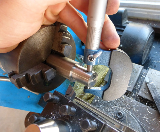
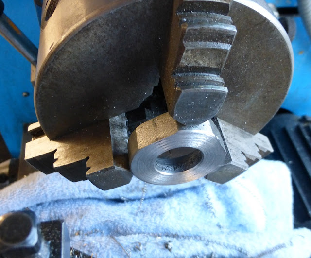
Somehow, this was the only way I could hold the next piece in the lathe to turn the diameter to match that of the bearing I removed.
The scrap piece fit into where the bearing was.
Pretty clean.
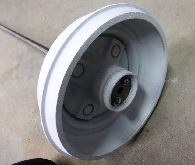
Guess what color White's mic stand gets painted? Hey, that doesn't look like semi-gloss, more like snow powder, seems the paint was clogged at first...
The base pieces connected.
Now for the height adjustment, I decided to make a collet, first turning the diameter to fit into the 7/8" tubing.
Almost fit except for the weld seam inside the tubing.
Filing the seam.
Next before threading it, looking in the machinist's handbook to get the diameter dimension.
 |
| Maurice, we need mo' rice! |
Checking the thread with a nut.
Then drilling and boring for the 5/8" tube.
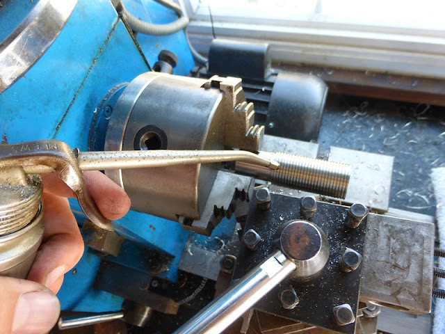
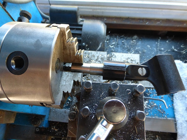
Then threading a 5/8"-27 thread for the microphone clip. I want to know the menace who decided that 27 threads per inch would be the standard for microphone stands.... it's not even a standard thread size, and several of the lathes I've encountered don't even have 27 as an option. But mine does!
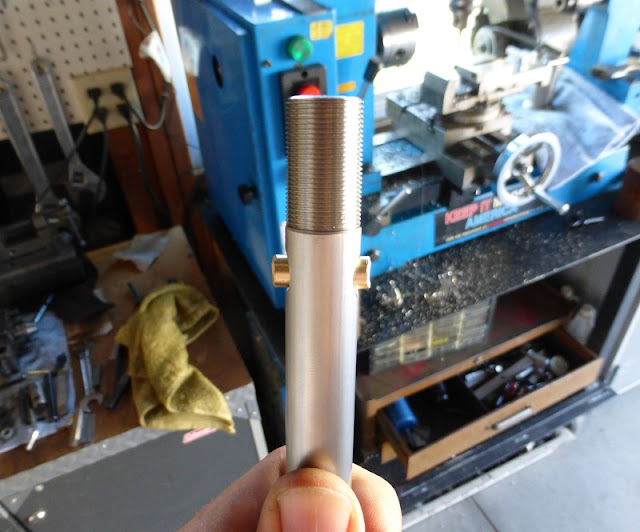
Now instead of welding this stuff together, I decided to use a brass rivet.
Gives a much cleaner look too.
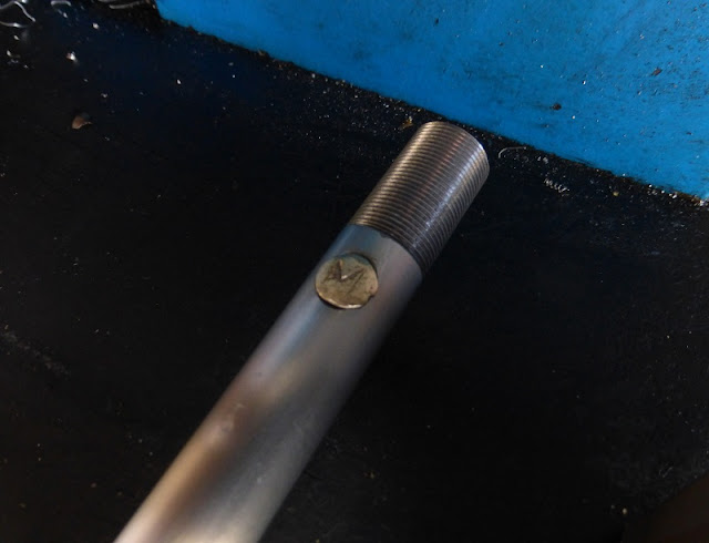
Then after flattening the ends, I figured I'd letter stamp an M & W on either side.
Mostly successful, though letter stamping a curved surface proved to be harder than expected.
With the rivet I accidentally made an "anti-falls-through-the-floor" mechanism. This picture shows the hacksawing I did to make the collet.
At first I thought I could make the locking mechanism by putting some O-rings in internal groove I turned into the collet and then using the 7/8 nut to tighten it, which proved to be a massive failure.
Then I remembered I have a camera tripod that has a smarter collet mechanism, so I borrowed the design. First tapering the top of the collet.
I figured I'd use the nut to connect the collet with the 7/8" tubing, so I bored out half of the thread to 7/8".
The part in the lathe is the new locknut which I threaded internally with the 7/8" thread. I decided it would be easier to make the taper a separate piece so I could thread the piece all the way through. The scrap piece used for the tapered part happened to be a failed oil burner design.
Turning the taper in the scrap piece.
Then cutting off the part I needed.
Facing the tapered piece.
The tapered piece fit into the locknut which goes over the collet which clamps the 5/8" tube and fits into the 7/8" tube which is held on with the 7/8" nut.... If any of that made any sense, it might make even less after this diagram:
As unnecessarily complicated this is, it actually worked. I don't have any way to powder coat the locknut at the moment, so I decided to just draw some symbols from the inside cover of All n All.
 |
| The name is Jupiter!!!! |
I found some stick-on pads at a garage sale to protect the floor.
















No comments:
Post a Comment
Hi folks, please only leave comments relative to the blog post. All spam will be removed and spammers will be blocked.
Note: Only a member of this blog may post a comment.